Optical Dissolved Oxygen Sensors & Principles of Operation
The dissolved oxygen sensors discussed so far rely on electrochemical processes to generate signals indicating the dissolved oxygen level in aqueous solutions. However, this approach is not suitable for all applications. In particular, traditional polarographic sensors have a number of issues:
- High maintenance: These sensors require regular replacement of the electrolyte and membrane cap.
- Long startup time: Polarographic sensors must undergo a polarization process to remove any residual oxygen in the sensor prior to use. This process can take 2 to 8 hours.
- Accuracy issues: Polarographic sensors are susceptible to contamination by gases such as carbon dioxide, which can alter the pH of the electrolyte, and by mobile ions such as sulfides, which can foul the electrodes. These issues affect the accuracy of the sensor.
- Environmental requirements: Because polarographic sensors consume the oxygen they measure, they require a constant flow or agitation of the water to avoid local depletion of the measured oxygen and reduction in accuracy.
These shortcomings have motivated intense research into alternative methods of measuring DO. The most effective approach found so far is the optical DO sensor. Optical dissolved oxygen sensors normally consist of the following:
- Excitation light.
- Oxygen-sensing material, which is made of a luminescent dye, called luminophore, and the polymer matrix permeable to oxygen.
- Photodetector to measure the alterations in the emitted light characteristics of a luminophore in the absence or presence of oxygen.
In addition to addressing the shortcomings of traditional DO sensors listed above, optical DO sensors have a number of advantages:
- Less fouling from contaminants in the liquid (and therefore less signal drift).
- Faster response time.
- Immunity against electrostatic noise.
- Greater stability against pressure spikes.
Fluorescence Quenching and Phase Shift
Optical DO sensors operate on the principle of luminescence. In certain materials, called luminophores, electrons within the luminophore absorb the energy of the specific excitation light and reach an excited state. In this state, interactions with other molecules (e.g. oxygen) can take place since the luminophore remains in the excited state for a defined time (fluorescence lifetime). When the electrons return from the excited state back to the ground state, they emit light, thus luminesce or fluoresce.
The interesting thing about luminophore materials is that the presence of oxygen gas (O2) in the excited state has two effects on the material’s fluorescence properties. When the oxygen molecule collides with the luminophore during the excited state, the energy is transferred from the luminophore to the oxygen and:
- The intensity of the emitter fluorescence is reduced.
- The fluorescence lifetime of the luminophore is shortened.
This phenomenon is called fluorescence quenching and is shown below.
Fluorescence Quenching Process

With optical DO sensors, fluorescence quenching can be measured by detecting changes in intensity and fluorescence lifetime. There is a relationship between the amount of oxygen present in the measurement sample and decrease in fluorescence intensity and/or fluorescence lifetime, which is described by the Stern-Volmer equation. Thus, by detecting and measuring one of these properties of the emitted light, the amount of oxygen present in the sample can be determined.
The Stern-Volmer Equation
Both the change in fluorescence intensity and the phase shift are correlated with the concentration of dissolved oxygen. This relationship is called the Stern-Volmer equation:

Where:
I = the measured fluorescence intensity
I0 = the reference (oxygen-free) fluorescence intensity
τ = the measured lifetime
τ0 = the reference (oxygen-free) lifetime
KSV = the fluorescence quenching constant, which is a property of the fluorescent material
[O2] = the concentration of oxygen
The simplicity and linearity of the Stern-Volmer equation simplifies the task of converting either the measured intensity or measured lifetime to an electronic signal that represents the dissolved oxygen concentration.
The first optical DO sensors relied solely on intensity. They suffered from accuracy issues over long periods of use because of factors such as fading of the dye compound and physical damage to the luminophore.
However, using phase shift as a measure of DO concentration has some advantages over intensity. The relationship between phase shift and oxygen concentration follows a stable, predictable pattern. In addition, phase shift is less sensitive to physical damage to the luminophore. As a result, more-recent optical DO sensor designs rely on phase shift rather than intensity.
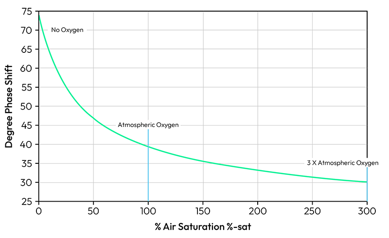
Relationship Between Dissolved Oxygen and Phase Shift
Optical DO Sensor Components
A basic optical DO sensor consists of the following components:
- A light source.
- A transmission medium (either a fiber optic or a window through which the light travels from the source to the fluorescent material).
- The luminophore (fluorescent dye suspended in a silicone gel matrix) that comes in contact with the aqueous solution.
- A photodetector to detect the light emitted from the fluorescent dye.
- Electronic circuitry to convert the detected fluorescence intensity and/or lifetime to an electronic signal.
Although the concept of fluorescence quenching was first described scientifically in 1939, it wasn’t until the late 20th century that the technology started attracting intense research interest, driven by the shortcomings of electrochemical DO detection and the improvements in light sources, photodetectors, and electronic signal processing.
Much of the research and development work in optical DO sensors has centered on the oxygen sensitive dye found in the luminophore. Several luminescent compounds are suitable for the optical DO sensor application; they fall into three main classes:
- Polycyclic aromatic compounds.
- Platinum-based compounds.
- Ruthenium-based compounds.
Each luminophore material has advantages and disadvantages for optical DO sensing. The exact material used in a given commercial sensor is often a strict trade secret.
The light source and photodetector are also critical components. Because each dye material fluoresces at a different wavelength of incident light, the light source, usually a light-emitting diode (LED), must be tuned to the correct wavelength. Similarly, the photodetector must be capable of detecting the intensity and phase of the fluorescent emission of the dye material.

Compensation
The performance of fluorescence-quenching optical DO sensors can be affected by various environmental and operational factors, such as temperature, pressure, and component aging. To maintain accurate readings and extend the useful life of the device, the effects of these factors must be compensated.
- Temperature: Changes in the temperature of the water being analyzed can alter the quenching effect of the dissolved oxygen, resulting in a reduction in sensor accuracy. Most commercial optical DO sensors incorporate a temperature sensing component. The electronic circuitry uses the temperature signal to correct the DO reading.
- Pressure: The pressure of the ambient air can also cause accuracy issues. The solubility of gas in water depends on the partial pressure of the gas, which is affected by altitude and weather conditions. Most optical DO measurement systems enable the user to enter the value of local atmospheric pressure. The system uses this value to correct the DO reading.
- Salinity: The amount of dissolved salt (NaCl) in the water also affects the solubility of oxygen gas. As with the case of pressure compensation, salinity compensation can be achieved by manual input based on a separate salinity measurement.
To learn more about compensation and sources of error review the Hamilton white paper: Measurement Challenges with Optical Dissolved Oxygen Sensors.
VisiFerm® ECS
Hamilton’s VisiFerm sensors with electrochemical signal (ECS) output transform the photodetector output to the nano-ampere (nA)-level output that is typical of traditional polarographic DO sensors. The ECS interface is a good choice for replacing polarographic sensors connected to existing bioreactors. In addition, most DO transmitters currently on the market require an nA signal, thus the Visiferm ECS can be retrofitted to work with these products. The output from an NTC 22-kΩ temperature sensor is also included to enable temperature compensation by external electronic circuitry.
VisiFerm® RS-485
VisiFerm RS-485 DO sensors incorporate a built-in micro-transmitter within the sensor. The output of these sensors is either 4–20 milliampere (mA) analog output or a Modbus digital signal. Hamilton’s Arc technology compensates for temperature changes and adjusts for input pressure and salinity values, all within the sensor with no need for external compensation circuitry. The output signal is therefore fully compensated. One advantage of this design is that VisiFerm RS-485 sensors can be directly connected to the process control system (PCS) without the need for a secondary transmitter.

Download Our O2 Measurement Guide
Get a better understanding of O2 measurement in Hamilton’s comprehensive O2 Measurement Guide.