Principles of Polarographic Measurement
One of the most common devices for measuring dissolved oxygen (DO) concentration in water is a polarographic dissolved oxygen sensor. A polarographic dissolved oxygen sensor operates by inducing an electrochemical reaction with the dissolved oxygen; the resulting electrical signal indicates the DO concentration. Learn what a polarographic dissolved oxygen sensor is, and the difference between optical and polarographic dissolved oxygen measurement.
The basic design of a polarographic dissolved oxygen sensor consists of a working electrode (cathode), a counter electrode (anode), a reference electrode, a voltage source, and an electrical current detector.
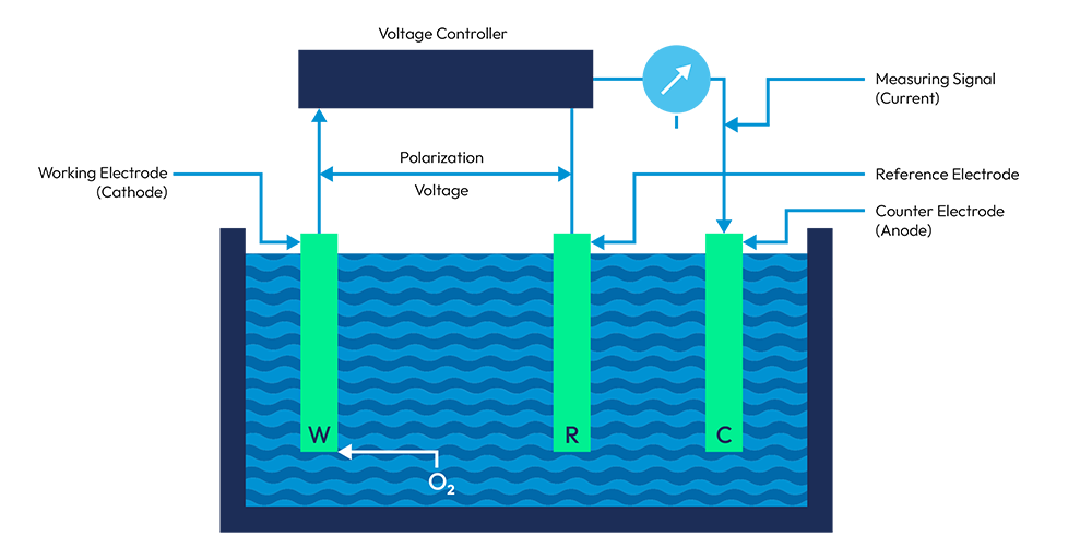
Schematic diagram of a polarographic oxygen sensor
The voltage source applies a small voltage, referred to as a polarization voltage, between the working electrode and the counter electrode. The dissolved oxygen undergoes a reduction reaction at the working electrode:
The source of the electrons (e− ) in the equation is the counter electrode. The counter electrode, typically made of silver (Ag) or silver chloride (AgCl), undergoes an oxidation reaction that releases electrons into the water:

This electron flow (electrical current) from the anode to the cathode represents the measuring signal, which is proportional to the partial pressure of the oxygen in the measured solution.
These reactions do not start automatically; the polarization voltage must be greater than the standard redox potential (+401 mV) of the reaction at the cathode, but with reversed polarity. This negative polarization voltage must be absolutely constant and stabilized against the reference electrode.
The standard redox potential is measured against the standard hydrogen electrode; the Ag/AgCl reference electrode itself has a potential difference of +210 mV against the standard hydrogen electrode. The applied polarization voltage must, therefore, be the sum of both voltages: −(401 + 210) = −611 mV. This is only an indication value; as discussed below, the actual applied polarization voltage is much higher.
Composition of Polarization Voltage
If the applied polarization voltage is too low, for example below −200 mV, no oxygen reduction can take place at the cathode. The applied voltage must be raised above that value in order to start the reduction that consumes electrons at the cathode. This condition initiates an electron flow from the anode to the cathode. Under increasing applied voltage, the current increases steeply until a plateau is reached at approximately −600 mV. Further voltage increases do not raise the current significantly. Under this condition the chemical reaction proceeds so fast that all oxygen molecules at the cathode are reduced, and the resulting electron flow (the measuring current) depends only on the oxygen concentration in the measured solution.

Diffusion Plateau
As shown in the image to the right, in the partial reduction zone, the polarization voltage is insufficient to enable a total reduction of all dissolved oxygen molecules at the cathode. At the diffusion plateau, the current no longer depends on the polarization voltage. All oxygen molecules at the cathode are reduced. The current is proportional to the quantity of oxygen molecules in the sample solution.
The design operating point of the device should be in the middle of the diffusion plateau.
The oxygen concentration at the working electrode is not necessarily representative of the oxygen concentration in the entire sample solution. Oxygen molecules are constantly reduced, and, therefore, the oxygen concentration decreases continuously at the cathode. To overcome this problem, the measured solution must be stirred or agitated to deliver fresh oxygen molecules to the working electrode. However, there will always be a small unstirred boundary layer at the cathode surface, no matter how strong the stirring action. Only by diffusion can the oxygen molecules reach the cathode surface. The electron flow is thereby governed by this diffusion, and thus the current at the diffusion plateau is called the diffusion current (ID).


Download Our O2 Measurement Guide
Get a better understanding of O2 measurement in Hamilton’s comprehensive O2 Measurement Guide.